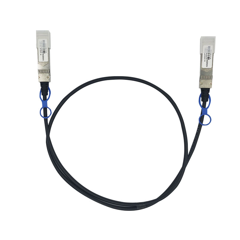
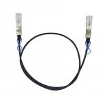
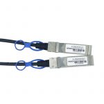
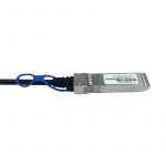
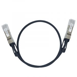
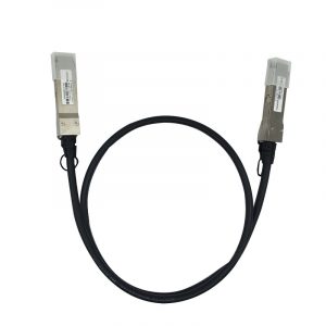
HX25-SFP28-DAC1 Direct Attach Cables are compliant with SFF-8432 and SFF-8402 specifications. Various choices of wire gauge are available from 30 to 26 AWG with various choices of cable length (up to 5m).
Specifications of 25G SFP28 Direct Attach Cable
Mechanical SpecificationsOrdering Information
Parameter
Minimum
Typical
Maximum
Unit
Cable Diameter (26AWG)
–
0.220
–
Inches
Bend Radius (26AWG)
1.102
–
–
Inches
Cable Diameter (28AWG)
–
0.185
–
Inches
Bend Radius (28AWG)
0.925
–
–
Inches
Cable Diameter (30 AWG)
–
0.181
–
Inches
Bend Radius (30 AWG)
0.906
–
–
Inches
Within Pair Skew
–
–
100
ps/10m
Cable Insertion Loss
–
15.43
–
dB/5m
Bulk Cable Time Delay
–
5.2
ns/m
Bulk Cable Impedance
95
100
105
Ohms
Insertion Force
–
–
40
N
Withdrawal Force
–
–
30
N
Retention Force
90
–
–
N
Durability
50 Cycles
–
–
–
ow EMI radiation Switches, servers and routers
Data Center networks
Storage area networks
High performance computing
Telecommunication and wireless infrastructure
Medical diagnostics and networking
Test and measurement equipment
Recommended Operation Condition of 25G SFP28 Direct Attach Cable
Parameter
Symbol
Min
Max
Unit
Operating Case Temperature
Topc
0
70
degC
Storage Temperature
Tst
-40
85
degC
Relative Humidity (non-condensation)
RS
35
60
%
Supply Voltage
VCC3
3.135
3.465
V
Voltage on LVTTL Input
Vilvttl
-0.3
VCC3 +0.2
V
Power Supply Current
ICC3
-
15
mA
Total Power Consumption
Pd
-
0.05
W
Notes: Stress or conditions exceed the above range may cause permanent damage to the device. This is a stress rating only and functional operation of the device at these or any other conditions above those listed in the operational sections of this specification is not applied. Exposure to absolute maximum rating conditions for extended periods may affect device reliability.
Frequency Domain of 25G SFP28 Direct Attach Cable
Item
Test Parameter
IEEE802.3bj Specification
1
Differential Insertion Loss (SDD12)
Maximum insertion loss at 12.8906Ghz @22.48dB
Minimum insertion loss at 12.8906Ghz@8dB
2
Differential Insertion Loss (SDD21)
Maximum insertion loss at 12.8906Ghz@22.48dB
Minimum insertion loss at 12.8906Ghz@8dB
3
Differential Return Loss (SDD22)
-16.5+2xSQRT(f) @ 0.01 to 4.1GHz
-10.66+14xLog10(f/5.5) @4.1 to 19GHz
4
Differential Return Loss (SDD11)
-16.5+2xSQRT(f) @ 0.01 to 4.1GHz
-10.66+14xLog10(f/5.5) @4.1 to 19GHz
5
Common Mode Reflection (SCC22)
-2dB @ 0.01 to 19GHz
6
Common Mode Reflection (SCC11)
-2dB @ 0.01 to 19GHz
7
Common Mode Conversion (SCD22)
-22+(20/25.78)*(f) @ 0.01 to 12.89GHz
-15+(6/25.78)*(f) @ 12.9 to 19GHz
8
Common Mode Conversion (SCD11)
-22+(20/25.78)*(f) @ 0.01 to 12.89GHz
-15+(6/25.78)*(f) @ 12.9 to 19GHz
9
Differential to Common Mode Conversion Loss (SCD12)
-10dB @ 0.01 to 12.89GHz
-27+(29/22)*(f) @ 12.9 to 15.7GHz
-6.3dB @ 15.71 to 19GHz
10
Differential to Common Mode Conversion Loss (SCD21)
-10dB @ 0.01 to 12.89GHz
-27+(29/22)*(f) @ 12.9 to 15.7GHz
-6.3dB @ 15.71 to 19GHz
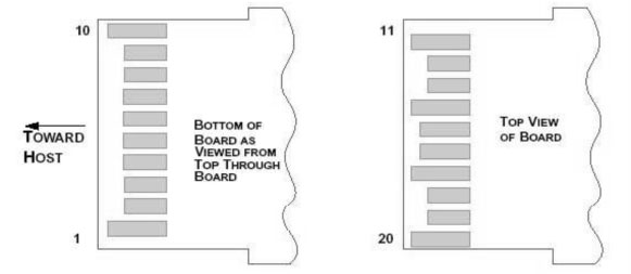
Pin
Symbol
Name/Description
1
VEET [1]
Transmitter Ground
2
Tx_FAULT [2]
Not used
3
Tx_DIS [3]
Not used
4
SDA [2]
2-wire Serial Interface Data Line
5
SCL [2]
2-wire Serial Interface Clock Line
6
MOD_ABS [4]
Module Absent. Grounded within the module
7
RS0 [5]
Not used
8
RX_LOS [2]
Loss of Signal indication. Logic 0 indicates normal operation
9
RS1 [5]
Not used
10
VEER [1]
Receiver Ground
11
VEER [1]
Receiver Ground
12
RD-
Receiver Inverted DATA out. AC Coupled
13
RD+
Receiver DATA out. AC Coupled
14
VEER [1]
Receiver Ground
15
VCCR
Receiver Power Supply
16
VCCT
Transmitter Power Supply
17
VEET [1]
Transmitter Ground
18
TD+
Transmitter DATA in. AC Coupled
19
TD-
Transmitter Inverted DATA in. AC Coupled
20
VEET [1]
Transmitter Ground
Notes: 1.Module circuit ground is isolated from module chassis ground within the module. 2..should be pulled up with 4.7k – 10k ohms on host board to a voltage between 3.15Vand 3.6V. 3.Tx_Disable is an input contact with a 4.7 kΩ to 10 kΩ pullup to VccT inside the module. 4.Mod_ABS is connected to VeeT or VeeR in the SFP+ module. The host may pull this contact up to Vcc_Host with a resistor in the range 4.7 kΩ to10 kΩ.Mod_ABS is asserted “High” when the SFP+ module is physically absent from a host slot. 5. RS0 and RS1 are module inputs and are pulled low to VeeT with > 30 kΩ resistors in the module.
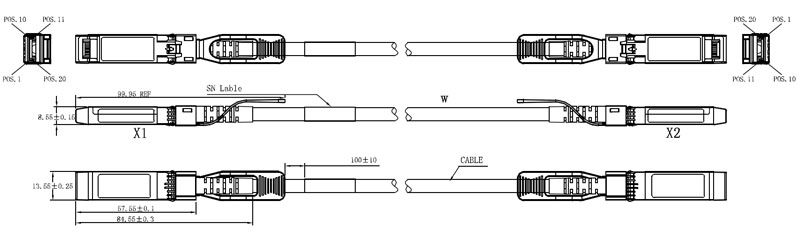
The connector is compatible with the SFF-8432 specification.
 HANSUN